Flow Measurements
Case Study
Flow Measurements at Eraring Power Station
Eraring Power Station is one of two coal fired electricity power stations with four 720 MW Toshiba steam driven turbo-alternators for a combined capacity of 2,880 MW. The station is located near the township of Dora Creek, on the western shore of Lake Macquarie, New South Wales, Australia and is owned and operated by Eraring Energy. The cooling water flow for steam condensation (main turbine condensers and steam feed pump condensers) is drawn from Bonnell’s Bay, Lake Macquarie, passing under Dora Creek through a concrete tunnel (caisson) and open canal. There was a need to measure the flow rate in the inlet canal and to determine how it varied as each of the six pumps was operated.
Teledyne RDI StreamPro Acoustic Doppler Current Profiler (ADCP)
A StreamPro ADCP was selected as the safest and most reliable way to gather data in the channel. The desired measuring location was location directly upstream from by large rotating drum screens and pumps used to lift the inlet canal water to a higher level canal. The screens and pumps represented a hazard to personnel so that no entry to the canal was permitted.
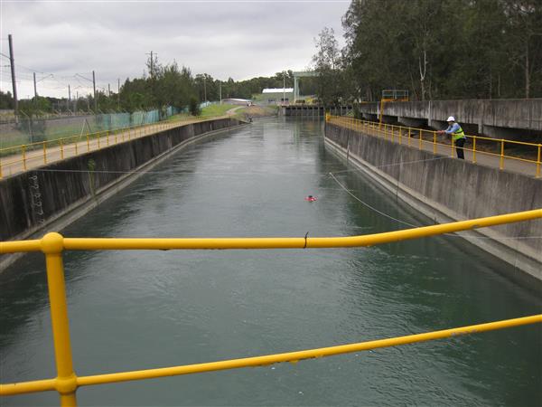
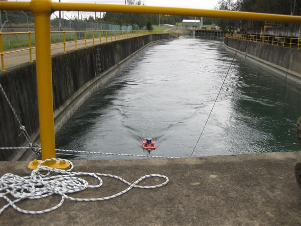
Using a combination of ropes and pulleys the ADCP was dragged across the inlet channel at Eraring Energy Power Station. The ‘bottom tracking’ capability of the StreamPro was used to move continuously across the stream to obtain a discharge measurement in two or three minutes instead of thirty minutes to an hour using the older point-by-point method.
The flow was tested at two different locations downstream from the bridge on the site. Measurements were conducted with six pumps available at the inlet channel in operation, so the flow was at its maximum possible value, and also with four pumps were in operation.
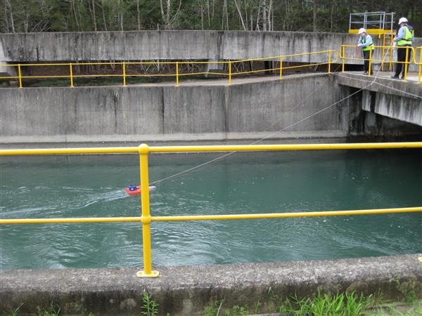
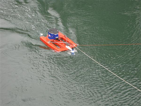
At each location a number of transects were performed with the ADCP from left to right and right to left. The data was collected using a hand held Personal Digital Assistant (PDA), which allowed for a confidence check of the data obtained while still on site. A more detailed analysis of the data was performed offsite using the Teledyne RDI software.
At each location a number of transects were performed with the ADCP from left to right and right to left. The data was collected using a hand held Personal Digital Assistant (PDA), which allowed for a confidence check of the data obtained while still on site. A more detailed analysis of the data was performed offsite using the Teledyne RDI software.
Results
Figure 1 shows the ADCP moved from the left wall to the right wall of the channel, and as a result the fast flowing water (which happens on the left of the channel, due to the bend) shows in the first ensembles (orange/red section).
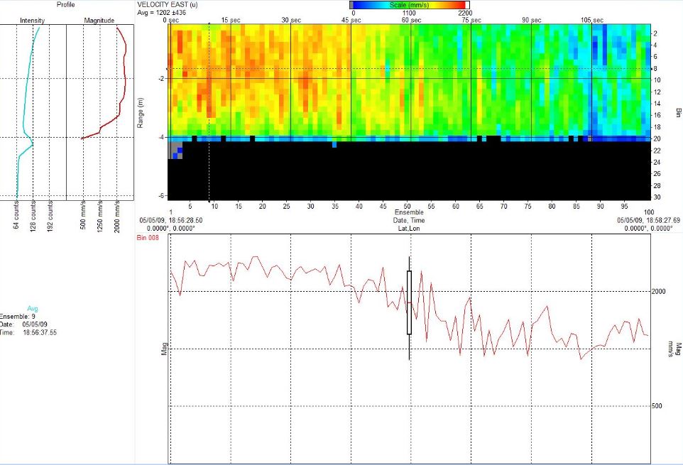
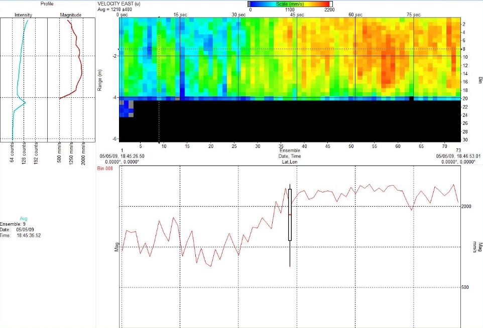
Figure 2 shows the ADCP moved from right to left, and therefore the fast flowing water shows in the last ensembles, to the right of the plot. The flow measured on the fast side of the channel (towards the left wall), and up to a depth of 3 m, was approximately 2.2 m/s. This measurement was consistent across the eight transects taken. The depth of the channel was found to be 4.3 m. Close to the channel bed the flow was considerably slower than on the surface..
